|
Nanjing Conpo Power Tech. Co., Ltd
|
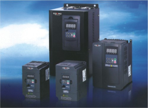
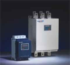
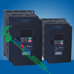
ZVF Series Vector Control Frequency Inverter
| Place of Origin: | Jiangsu, China (Mainland) |
|
|
|
| Add to My Favorites | |
| HiSupplier Escrow |
Product Detail
.
Feature:
1. Advanced vector control algorithm, combine with accurate speed calculation and self learning of the motor parameter. It realize the accuracy control of motro speed and torque under sensorless vector control mode. V/F and SVC can be selected.
2. Optimized space voltage vector PWM modulation technology, has over-modulation function, high voltage-utilization rate, low output harmonic wave, and it greatly improves the stability and switcihng loss of the motor.
3. Good operation characteristic of low frequency, can realize 0.5Hz/150% rated torque output which is under sensorless vector control mode.
4. LCD and LED double display keyboard, display digit and Chinese, the user can operate easily.
5. Control terminal analog voltage output, current output, digit output, impulse output, voltage current, impulse, communication and other.
6. Multi frequency setting modes, also can realize the overplay function for all kinds of given source, and the frequency control mode is very flexible.
7. Abundant functions: Automatic voltage regulation control, automatic slip compensation, restart when the power cuts and so on. Can meet the demand of different users.
8. Customization function design: Program running, wobble frequency running, PID control operation, timing function, counter function and ect. Can be convenient to form and meet the dfferent industrial field demands;
9. Built-in RS485 interface, compat with MODEBUS commmunication proteocol, can realize networked control.
10. Super strong protect function: Over voltage, over current, over load, under voltage, over heat, short circuit and so on, can offer more than 20 kinds failure prtoection function for user.
Specification:
| Item | |||||||||||
| Remark: | |||||||||||
| ZVF9V-G 0075 T4 DR(for example), Model description: G means General type; P means Pump type T4 means 3phase 380V; T2 means 3phase 220V; S2 means 1phase 220V DR means there is a braking unit inside; No DR means without braking unit inside |
| Model | General-type | Model | General-type | Model | Pump-type | |||||
| ZVF9V-G0007S2 | 0.75KW/220V/1P | ZVF9V-G0220T4 | 22KW/380/3P | ZVF9V-P0015T4 | 1.5KW/380/3P | |||||
| ZVF9V-G0015S2 | 1.5KW/220V/1P | ZVF9V-G0300T4 | 30KW/380/3P | ZVF9V-P0022T4 | 2.2KW/380/3P | |||||
| ZVF9V-G0022S2 | 2.2KW/220V/1P | ZVF9V-G0370T4 | 37KW/380/3P | ZVF9V-P0037T4 | 3.7KW/380/3P | |||||
| ZVF9V-G0037S2 | 3.7KW/220V/1P | ZVF9V-G0450T4 | 45KW/380/3P | ZVF9V-P0040T4 | 4KW/380/3P | |||||
| ZVF9V-G0550T4 | 55KW/380/3P | ZVF9V-P0055T4 | 5.5KW/380/3P | |||||||
| ZVF9V-G0007T2 | 0.75KW/220V/3P | ZVF9V-G0750T4 | 75KW/380/3P | ZVF9V-P0075T4 | 7.5KW/380/3P | |||||
| ZVF9V-G0015T2 | 1.5KW/220V/3P | ZVF9V-G0900T4 | 90KW/380/3P | ZVF9V-P0110T4 | 11KW/380/3P | |||||
| ZVF9V-G0022T2 | 2.2KW/220V/3P | ZVF9V-G1100T4 | 110KW/380/3P | ZVF9V-P0150T4 | 15KW/380/3P | |||||
| ZVF9V-G0037T2 | 3.7KW/220V/3P | ZVF9V-G1600T4 | 160KW/380/3P | ZVF9V-P0185T4 | 18.5KW/380/3P | |||||
| ZVF9V-G0055T2 | 5.5KW/220V/3P | ZVF9V-G1850T4 | 185KW/380/3P | ZVF9V-P0220T4 | 22KW/380/3P | |||||
| ZVF9V-G0075T2 | 7.5KW/220V/3P | ZVF9V-G2000T4 | 200KW/380/3P | ZVF9V-P0300T4 | 30KW/380/3P | |||||
| ZVF9V-G0110T2 | 11KW/220V/3P | ZVF9V-G2200T4 | 220KW/380/3P | ZVF9V-P0370T4 | 37KW/380/3P | |||||
| ZVF9V-G0150T2 | 15KW/220V/3P | ZVF9V-G2500T4 | 250KW/380/3P | ZVF9V-P0450T4 | 45KW/380/3P | |||||
| ZVF9V-G0185T2 | 18.5KW/220V/3P | ZVF9V-G2800T4 | 280KW/380/3P | ZVF9V-P0550T4 | 55KW/380/3P | |||||
| ZVF9V-G0220T2 | 22KW/220V/3P | ZVF9V-G3150T4 | 315KW/380/3P | ZVF9V-P0750T4 | 75KW/380/3P | |||||
| ZVF9V-G3500T4 | 350KW/380/3P | ZVF9V-P0900T4 | 90KW/380/3P | |||||||
| ZVF9V-G0007T4 | 0.75KW/380/3P | ZVF9V-G3750T4 | 375KW/380/3P | ZVF9V-P1100T4 | 110KW/380/3P | |||||
| ZVF9V-G0015T4 | 1.5KW/380/3P | ZVF9V-P1600T4 | 160KW/380/3P | |||||||
| ZVF9V-G0022T4 | 2.2KW/380/3P | ZVF9V-P1850T4 | 185KW/380/3P | |||||||
| ZVF9V-G0037T4 | 3.7KW/380/3P | ZVF9V-P2200T4 | 220KW/380/3P | |||||||
| ZVF9V-G0040T4 | 4KW/380/3P | ZVF9V-P2500T4 | 250KW/380/3P | |||||||
| ZVF9V-G0055T4 | 5.5KW/380/3P | ZVF9V-P2800T4 | 280KW/380/3P | |||||||
| ZVF9V-G0075T4 | 7.5KW/380/3P | ZVF9V-P3150T4 | 315KW/380/3P | |||||||
| ZVF9V-G0110T4 | 11KW/380/3P | ZVF9V-P3500T4 | 350KW/380/3P | |||||||
| ZVF9V-G0150T4 | 15KW/380/3P | ZVF9V-P3750T4 | 375KW/380/3P | |||||||
| ZVF9V-G0185T4 | 18.5KW/380/3P | |||||||||
| Input | Rated voltage, frequency | Single/three-phase 220VAC, three-phase 380VAC, 50Hz/60Hz | |||||||||
| Allowable voltage range | Voltage fluctuation range: -20%~20% Voltage unbalance rate<3%; frequency fluctuation?+/-% | ||||||||||
| Output | Rated voltage | Three-phase 0~input voltage VAC | |||||||||
| Frequency | 0.00~400.00Hz | ||||||||||
| Overload capacity | Type: G: 150% 1min; 180% 1second; 200% transient protection | ||||||||||
| Type: G: 120% 1min; 150% 1second; 180% transient protection | |||||||||||
| Control function | Modulation method | Optimal space voltage vector PWM modulation | |||||||||
| Control method | Sensorless vector control(SVC) | ||||||||||
| Frequency accuracy | Digital setting: max. frequency x+/-0.01% Analog setting: Max. frequency x +/-0.2% | ||||||||||
| Frequency resolution | Digital setting: 0.01Hz Analog setting: Max. Frequency x 0.1% | ||||||||||
| Starting frequency | 0.00~10.00Hz | ||||||||||
| Torque lifting | Automatic torque lifting: to lift the torque automatically according to the output current. | ||||||||||
| Hand-operated torque lifting range: 0/1~30% | |||||||||||
| Slip compensation | Setting range:0~150%, the inverter output frequency can be auto-regulated within this range according to the motor load so as to reduce the speed variation of the motor due to load fluctuation | ||||||||||
| Acceleration/deceleration time | 0.1~3600.0sec/min, which can be set in sequence. | ||||||||||
| Carrier frequency | 1.0~15.0Khz | ||||||||||
| Jog function | Jog frequency range: 0.01~400Hz Jog acceleration/deceleration time, 0.1~3600 can be set. | ||||||||||
| V/F curve | Linear curve; 2. Quadratic(conic); 3. User define V/F curve | ||||||||||
| Control function | Automatic energy-saving operation | Auto optimize V/F curve according to load fluctuation to realize energy-saving operation | |||||||||
| Auto voltage regulation(AVR) | When the network voltage changes, it can regulate PWM output automatically to maintain constant voltage | ||||||||||
| Built-in PID | This can form a convenient closed-loop control system(CLCS), and is applicable to pressure control flow control and other process control. | ||||||||||
| Control | Operation command | Operator panel control, external terminal control and COM control | |||||||||
| function | DC braking | Panel potentiometer setting, operator panel setting, external terminal up/down setting, analog voltage signal or external potentiometer setting, analog current signal setting, analog assembly setting, 485 COM setting and etc. | |||||||||
| Input signal | Forward/reverse signal, multiple speed signal, failure signal output and etc. | ||||||||||
| Output signal | Programmable relay, open-collector output, failure signal output and etc. | ||||||||||
| Multi-function analog and digital output terminal | This can realize the output of frequency, current and other physical quantity by outputting 0~10V or 0~20Ma DC signal and 0~10KHz digital signal | ||||||||||
| Dynamic braking | With an external braking resistor, the maximum braking torque may reach 100% | ||||||||||
| DC braking | This can be selected when the motor starts or stops with the action frequency of 0~20Hz, action current level of 0~100% and actuation time of 0~30 sec., which can be set in sequence. | ||||||||||
| Braking function | Other functions | Leap frequency, jog function, counter, trace to rotating speed, instant shutdown restarting, frequency upper/lower limitation, acceleration/deceleration mode regulating, frequency meter and voltmeter output, multiple speed/program operation, two-wire/three control, vibration frequency control, multi-function input terminal selection, failure auto reset and 485COM | |||||||||
| Protection function | Input open-phase protection, over-current protection, overload protection, under voltage protection, overheating protection and tec. | ||||||||||
| LED, LCD Display | Real-time display the running state, monitoring parameters, function parameters, diagnostic trouble codes(DTC) and other information of the inverter. | ||||||||||
| Matching parts | Brake assembly, remote operator panel, connecting wire, communication panel. | ||||||||||
| Place to be used | Indoor location free from direct exposure to sunlight, high humidity or dew condensation, high levels of dust, corrosive gas, explosive gas, inflammable gas, oil mist, salt and etc. | ||||||||||
| Ambient | Altitude | Below 1000M | |||||||||
| Ambient temperature | -10~+45? | ||||||||||
| Humidity | 20~90%RH without dew condensation | ||||||||||
| Vibration | <0.5G | ||||||||||
| Storage temperature | -20~60? | ||||||||||
| Structure | Protective class | IP20 | |||||||||
| Cooling system | Forced air cooling | ||||||||||
| Installation | Wall mounted or floor-type actuator | ||||||||||
Related Search
Frequency Inverter
Mini Frequency Inverter
Adjustable Frequency Inverter
Inverter
Filter Series
Vf Series
More>>
Find more related products in following catalogs on Hisupplier.com
Company Info
Nanjing Conpo Power Tech. Co., Ltd [China (Mainland)]
Business Type:Manufacturer
City: Nanjing
Province/State: Jiangsu
Country/Region: China (Mainland)
|
Franceconpo:
|